Are you tired of dealing with electrical issues that seem to come out of nowhere? Imagine being able to pinpoint the exact spot where the problem lies, saving you time, money, and a lot of frustration.
This is where electrical continuity testing becomes your best friend. In this guide, you’ll discover how this simple yet powerful tool can transform your approach to electrical maintenance. From ensuring the safety of your home to enhancing the efficiency of your projects, understanding continuity testing is a game-changer.
Stick with us, and by the end of this article, you’ll have the confidence to tackle those electrical gremlins head-on with precision and ease. Ready to uncover the secrets of seamless electrical systems? Let’s dive in!

Credit: www.origin-ic.com
Basics Of Electrical Continuity
Electrical continuity testing checks if an electric path is complete. It helps find breaks in wires or circuits.
This test is simple but important for safety and function in electrical systems.
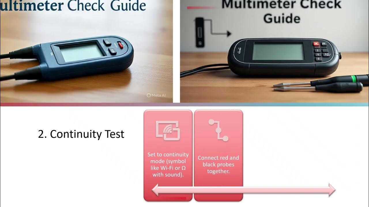
What Is Continuity Testing
Continuity testing shows if electricity can flow through a wire or circuit. If the path is unbroken, the circuit has continuity. If the path is broken, it does not.
Electricians use a tool to send a small current through the wire. The tool signals if the current passes through or stops.
Common Applications
- Checking wires in electrical panels
- Testing switches and outlets
- Finding breaks in extension cords
- Ensuring proper connections in appliances
- Verifying fuse and circuit breaker function
Tools Required
| Tool | Purpose |
| Multimeter | Measures continuity and resistance |
| Continuity Tester | Simple device that beeps for continuity |
| Test Leads | Connect tester to the circuit |
| Insulated Gloves | Protect against electric shocks |

Credit: www.youtube.com
Types Of Continuity Testers
Electrical continuity testers check if a circuit is complete. They help find breaks or faults in wiring.
This guide explains three main types of continuity testers. Each type works in a different way.
Multimeters
Multimeters are common tools for measuring voltage, current, and resistance. They also test continuity with a sound or light signal.
- Show if a circuit is open or closed
- Use a beeping sound to indicate continuity
- Measure resistance to check wire quality
- Can test other electrical values too
Dedicated Continuity Testers
These testers are made only for checking continuity. They are simple and easy to use.
| Feature | Benefit |
| Single function | Easy to operate |
| Visual or sound alert | Quick feedback |
| Low cost | Affordable for basic testing |
| Compact size | Portable and handy |
Advanced Testing Devices
Advanced devices combine continuity testing with other diagnostic tools. They offer detailed analysis and better accuracy.
- Digital displays with multiple readouts
- Data logging for tracking test results
- Bluetooth connection for mobile apps
- Auto-ranging for quick measurements
- Built-in fault location functions
Preparing For Continuity Testing
Electrical continuity testing helps check if a circuit is complete. It ensures that electricity can flow through wires and components.
Before testing, you must prepare carefully. Proper preparation keeps you safe and gives accurate results.
Safety Precautions
Safety is the top priority before testing electrical circuits. Always protect yourself and others around you.
Wear insulated gloves and safety glasses. Avoid loose clothing or jewelry that can catch on equipment.
- Turn off power to the circuit
- Use insulated tools only
- Work in a dry area
- Keep hands dry and steady
- Check for damaged wires before testing
Equipment Setup
Choose the right testing tool like a multimeter set to continuity mode. Check that the tool works before use.
Prepare the test leads. Make sure they are clean and free from damage. Connect them properly to the tester.
- Select continuity mode on the tester
- Inspect test leads for cracks or breaks
- Attach test leads firmly to the tester
- Test the meter on a known circuit before use
Circuit Isolation
Isolate the circuit before testing to avoid wrong readings and accidents. Remove power and disconnect components if needed.
Check that no voltage is present using a voltage tester. Isolation stops current from flowing and protects you during testing.
- Turn off all power sources
- Disconnect batteries or power supplies
- Separate the circuit from other connected circuits
- Use a voltage tester to confirm no power
Step-by-step Testing Procedure
Electrical continuity testing checks if a circuit is complete. It helps find breaks or faults in wires and components.
This guide explains how to test continuity safely and correctly using a tester or multimeter.
Connecting The Tester
First, turn off power to the circuit. This prevents shocks or damage to the tester.
Next, connect the tester probes to both ends of the wire or component you want to test.
- Touch one probe to one end of the circuit
- Touch the other probe to the opposite end
- Ensure firm contact for accurate readings
Interpreting Results
Look at the tester display or listen for sounds to understand the result. Most testers beep if continuity exists.
If the tester shows zero or near zero resistance, the circuit is complete. High or infinite resistance means a break.
- Low resistance means good continuity
- High resistance means broken connection
- No sound or reading means no continuity
Common Indicators
Testers use different signs to show continuity. Knowing these signs helps you read results fast.
| Indicator | Meaning |
|---|---|
| Beep sound | Continuity exists |
| 0 or low resistance | Complete circuit |
| OL or infinite resistance | Broken circuit |
| No beep or display | No continuity |
Factors Affecting Accuracy
Electrical continuity testing checks if an electrical path is complete. Accuracy is important to get correct results. Some factors can change how accurate the test is.
This guide explains three key factors that affect accuracy. Knowing these helps improve your testing process.
Contact Resistance
Contact resistance is the resistance at the point where the tester touches the wire or component. High contact resistance can cause false readings.
- Dirty or corroded contacts increase resistance.
- Loose connections reduce the test quality.
- Worn test leads can affect contact resistance.
- Proper pressure on the contact point lowers resistance.
Environmental Influences
Temperature and humidity affect test results. Extreme conditions may change how electricity flows through the circuit.
| Environmental Factor | Effect on Accuracy |
| High Temperature | Can lower resistance, causing false continuity |
| Low Temperature | May increase resistance, leading to missed faults |
| High Humidity | May cause corrosion and false readings |
| Dust and Dirt | Interferes with contact points |
Tester Calibration
Calibration keeps the tester accurate. Without it, the device may give wrong results over time.
- Check calibration regularly as per the manufacturer’s guide.
- Use certified calibration tools or services.
- Record calibration dates and results for reference.
- Recalibrate if the tester is dropped or damaged.
Troubleshooting Common Issues
Electrical continuity testing helps check if a circuit is complete. It finds breaks or faults in wiring and devices. Sometimes tests show wrong results that cause confusion.
Knowing common issues helps fix problems faster. This guide covers false positives and negatives, intermittent connections, and damaged components.
False Positives And Negatives
False positives happen when the tester shows continuity but the circuit is broken. False negatives occur when the tester shows no continuity but the circuit is fine.
- Loose test leads can cause false readings.
- Dirt or corrosion on contacts may block signals.
- Incorrect tester settings can give wrong results.
- Using a low battery tester reduces accuracy.
- High resistance components may appear open or closed wrongly.
Intermittent Connections
Intermittent connections work sometimes and fail other times. They cause unpredictable test results and device issues.
| Cause | Effect | Solution |
| Loose wire or terminal | Signal cuts in and out | Tighten or resolder connection |
| Broken wire inside insulation | Intermittent open circuit | Replace damaged wire |
| Oxidation on contacts | Poor conductivity | Clean or replace contacts |
| Vibration or movement | Connection breaks under stress | Secure wiring and connectors |
Damaged Components
Damaged components can block current flow or cause shorts. They often cause failed continuity tests.
Common damaged parts include:
- Burned resistors or fuses
- Cracked circuit boards
- Broken connectors or terminals
- Swollen or leaking capacitors
Always inspect parts visually and test individually if possible.
Best Practices For Reliable Testing
Electrical continuity testing checks if circuits are complete and safe. Reliable testing ensures devices work well and avoid hazards.
Follow simple steps to get accurate results every time you test electrical circuits.
Regular Equipment Maintenance
Keep your testing tools clean and in good shape. Damaged or dirty equipment can give wrong readings.
Check meters and probes often. Replace worn parts to keep tests accurate and safe.
- Clean probe tips with a soft cloth
- Check battery levels before testing
- Inspect cables for cuts or damage
- Store tools in a dry, safe place
Proper Connection Techniques
Connect test leads firmly to the circuit points. Loose connections cause false results or no reading.
Make sure the circuit is off before testing. Use proper probes that fit well on terminals.
- Use correct polarity when connecting leads
- Avoid touching probe tips during testing
- Secure connections to avoid slipping
- Test on clean, bare metal surfaces
Documentation And Reporting
Write down test results clearly and immediately. Good records help track issues and fixes.
Use a standard format for reports. Include date, equipment tested, and any problems found.
- Date and time of test
- Equipment or circuit name
- Test results and readings
- Notes on any defects or repairs
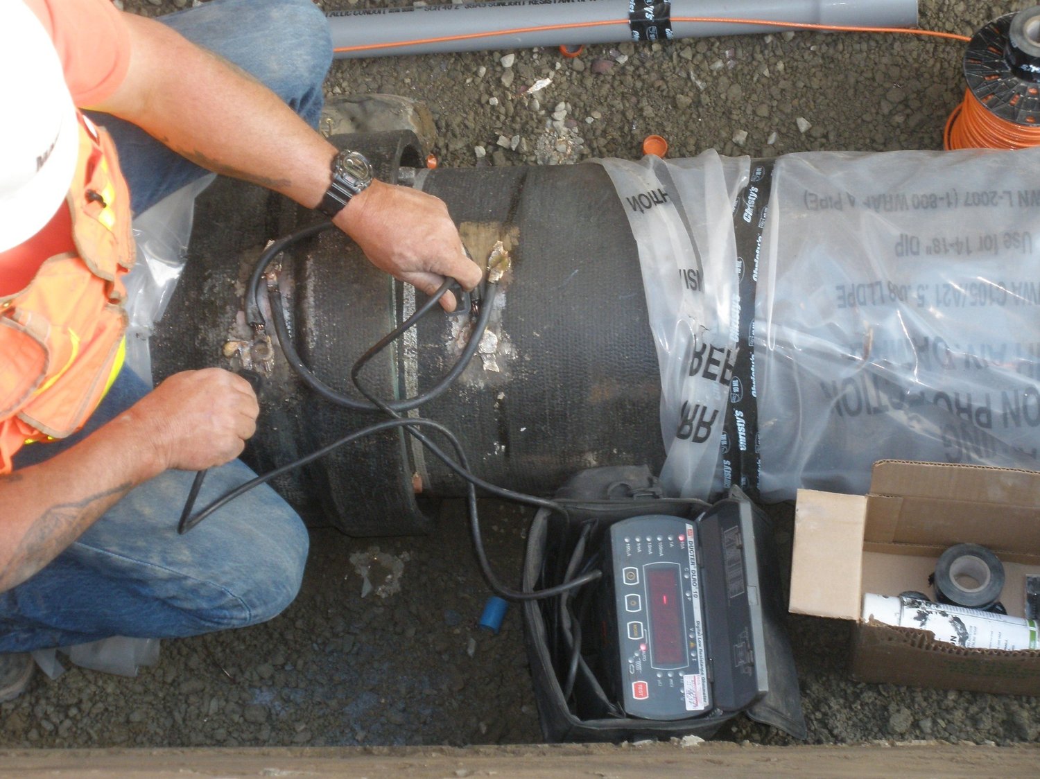
Credit: www.vaengineering.com
Advanced Tips And Techniques
Electrical continuity testing helps check if a circuit is complete. It shows if current can flow through wires or parts.
Advanced tips improve testing in complex systems. These techniques save time and increase accuracy.
Using Continuity Testing In Complex Circuits
Complex circuits have many parts connected together. Testing one part without affecting others is important.
Use these tips to test complex circuits effectively:
- Disconnect power to avoid damage or false readings.
- Test wires one at a time to find breaks or shorts.
- Use test leads with sharp tips for small connectors.
- Label wires to keep track of your tests.
- Check for components like resistors or capacitors that affect readings.
Integrating With Other Diagnostic Methods
Continuity testing works well with other methods. Combining tests gives clearer results.
Common methods to use with continuity testing include:
- Voltage testing to check power presence.
- Resistance testing to measure component values.
- Visual inspection to spot broken wires or burns.
- Using circuit diagrams to understand connections.
Using these methods together helps find problems faster. It reduces guesswork in repairs.
Upgrading Testing Equipment
Better tools improve testing speed and accuracy. Modern testers offer more features and easy use.
Consider upgrading to equipment with these features:
- Digital displays for clear readings.
- Auto-ranging to simplify measurement settings.
- Built-in alarms to signal continuity.
- Data hold to save readings for later.
- Compact size for easy handling.
Good equipment helps avoid errors and speeds up troubleshooting. It also lasts longer in tough conditions.
Frequently Asked Questions
What Is Electrical Continuity Testing?
Electrical continuity testing checks if a circuit is complete, allowing current to flow without interruption.
How Do You Perform Continuity Testing Safely?
Turn off power, use a multimeter, and test across circuit points carefully.
Why Is Continuity Testing Important In Electrical Work?
It ensures circuits are properly connected, preventing faults and improving safety.
Can Continuity Testing Detect Broken Wires?
Yes, it identifies breaks or faults by showing no electrical flow.
Conclusion
Electrical continuity testing helps find breaks in circuits fast. It ensures wires and devices work properly and safely. Using the right tools makes testing easy and accurate. Regular checks prevent problems before they grow bigger. Keep your circuits reliable by testing often.
This simple step saves time and money. Trust your skills and equipment for best results. Stay safe and confident with every test you do.